We're in the year 2006, I'm 17 years old, I'm studying electronics since only a year and we are asked by the teacher to choose a project.
The requirements are easy and basic, we need to make something based on an existing schematic of our choice. The goal is to learn basic schematic drawing, component selection, pcb design, PCB manufacturing and of course soldering.
The project I chose, was an Infrared light barrier that would buzz when interrupted. This project seems very simple, but I learned lots of electronic concepts during those weeks of building.
Understanding the schematics
The first challenge was to understand the schematic. It's a two part project, first the Transmitter and secondly, the Receiver (let's call them IR-Tx and IR-Rx).
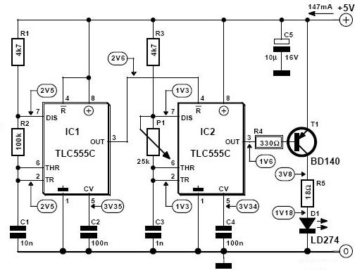
IR Transmitter based on 555 chip
The core component of the transmitter is the famous 555 timer. In this circuit it is used to modulate the infrared signal.
The 555 timer is an interesting chip to start learning about the internal working of integrated circuits, I'll probably make an article in the future about it.
I'll explain this simple modulation circuit by starting from the left.
The chip IC1 is generating a clock at approx. 700Hz with a duty cycle of 50%. (these values are determined by the capacitor C1 and the resistors R1 and R2).
IC2 is generating a clock going from 26kHz to 215kHz (value depends of potentionemer P1).
If you look closely, IC1 is driving IC2's reset pin, it means that during the low phases of IC1, IC2 is turned on (because it's an active low input). It's a simple form of signal modulation, where IC2 frequency is the carrier frequency. It means that during the low phases of IC1, the output signal (modulated signal), is clocking at 26kHz.
The modulated signal drives the PNP transistor T1 to turn on and off the infrared LED D1.
This LED creates a beam of infrared light which the receiver will detect if it's interrupted or not.
The reason for the signal to be modulated is more subtle than it seems. The frequency of IC2 is there to match the carrier frequency of the receiver, and will depend on the infra red light receiver module that you use. IC1, which is at lower frequency, has another purpose that I'm going to explain later in the receiver part.
Another advantage of sending a blockwave to the LED is that we can increase the current through it, and thus the emmiting power of the light.
IR LED's used in remote controls can draw more than 1A during a short amount of time, in this application it's drawing a bit over 200mA, which is still a lot for an infrared LED (it couldn't survive continuously this current). According to the datasheet, this LED can withstand 3A of current during 10us (Warning: Absolute Maximum ratings). It means that we could have reduced the resistor value of R5 or increased the voltage of the circuit to extend the range of the beam.
Capacitor C2 and C4 are just decoupling caps, I'll make an article about this subject in the future (todolist is growing).
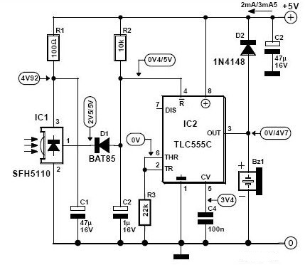
IR Receiver based on 555 chip
The receiver circuit also uses the 555 timer, let's say that this project is based on that chip !
The SFH5110 from OSRAM (component manufacturer specialized in lighting systems) is an infrared light receiver module. This integrated circuit only reacts to infrared light that is oscillated (modulated) at a certain frequency, the version I bought was for 36kHz. It means that his sensitivity for other frequencies drops and is inexistand for continuous light emission (sunlight). That's good for us, since we don't want our receiver to be interferred by other IR light sources.
When IC1 detects an infrared 36kHz beam, it will pull his pin 1 low such that diode D1 will conduct current (which is limited by R2) and pull the reset pin from IC2 low (active low pin) which will turn off the 555.
When nothing is detected by SFH5110 or the beam is interrupted, the output pin 1 will then turn on and block cuurent from D1 and pull the Reset pin from the 555 high (active low pin), this will turn the output pin 3 on.
The 555 is used here in a non traditional way, here it acts as a switch (overkill application). It will be ON or OFF depending of the reset pin (NOT-gate).
The buzzer is a piezzo based component that has an embedded oscillator. To make it buzz, a constant current needs to be applied, which is provided from the 555's output.
Conclusion: The circuit turns the buzzer on when the IR beam is interrupted. It's an overkilled application of 555's and other components, it could have been made much simpler, but the goal of this project was to learn new concepts like modulation, timers and driving loads.
Upgrade
When I was done with the project, I had a couple of weeks left before presenting it to the teacher. I thought about upgrading the project a little by using it as a people counter for a room, by counting the times the beam is interrupted at a door's entrance.
I used a binary counter from the 7400 series logic chips, than a BCD to 7 segment decoder to display the counter value on a 7 segment display.
I don't remember the name of the exact chips I used, at the time I didn't learned yet to document my work.
What I learned
This was my first real project in the electronics field, here some things I learned during those weeks.
- - Grab for help when you can't figure it out yourself (also offer help to other people).
- - Document your work, after a year you forget everything that's not written somewhere.
- - A project doesn't work from the first time, keep trying in different ways. Experiment !
- - Organization is key, a project can't be done in one night, some planning is needed.
- - READ datasheets, and understand what you read. Don't only scroll over the PDF files.
References
Schematic images are from the book 308 Schakelingen by Elektor.